
Part Number: DS200TCPDG1BCC
Manufacturer: General Electric
Series: MKV
Description:
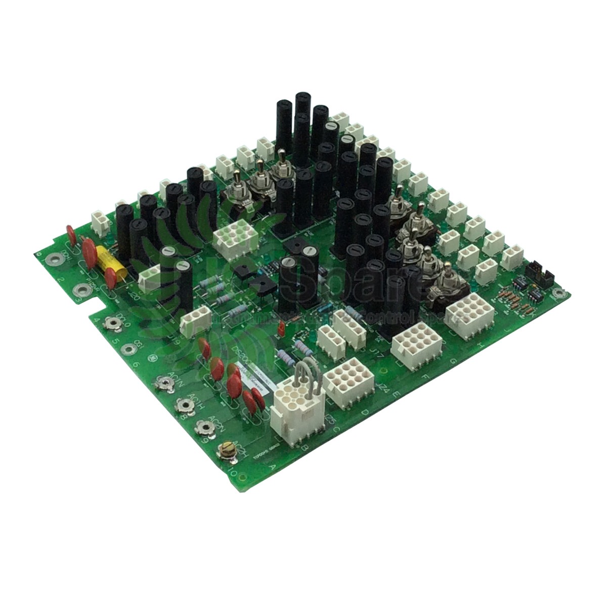
The DS200TCPDG1BCCT distributes power to various boards within the Mark V system, including the TCPS boards in each I/O core, the control engine core, and the TCEA boards in the P1 core. It features 36 fuses, eight toggle switches, and four signal wire terminals for efficient power distribution and monitoring. The board is equipped with 36 green “OK” LEDs to indicate the operational status of each fuse and two red LEDs to alert operators of any issues that require further investigation.
Type: Power Distribution Board
Model: DS200TCPDG1BCCT
Function: Power distribution and fuse monitoring
Fuses: 36 fuses
Switches: Eight toggle switches
Terminals: Four signal wire terminals
LED Indicators: 36 green “OK” LEDs, 2 red LEDs
Voltage Rating: 125 VDC
Fused Power Distribution: The board provides fused power distribution with 36 fuses for protection and safety.
LED Indicators: 36 green “OK” LEDs for fuse status monitoring and two red LEDs for issue alerts.
Toggle Switches: 8 toggle switches for manual control and operation.
Signal Wire Terminals: 4 signal wire terminals for efficient connectivity.
Voltage Rating: Rated at 125 VDC for compatibility with the Mark V system.
Location: Housed in the PD core within the MKV panel for easy access and maintenance.
The DS200TCPDG1BCCT is specifically designed for use with the GE Speedtronic Mark V turbine control systems. It is compatible with various subsystems within the Mark V system, ensuring seamless integration and reliable performance.
The DS200TCPDG1BCCT plays a crucial role in improving the performance of GE Mark systems by:
Enhancing Power Distribution: The board ensures efficient and reliable power distribution to critical components within the turbine control system.
Fuse Monitoring: The LED indicators allow for real-time monitoring of fuse status, enabling quick identification of any issues that may impact system performance.
Troubleshooting: The board’s design facilitates troubleshooting by providing clear visual indicators of fuse status and potential issues, allowing for prompt resolution and minimizing downtime.
The DS200TCPDG1BCCT is primarily used in gas turbine control, power generation, and industrial automation applications where reliable power distribution and fuse monitoring are essential for system operation and safety.
Fuse Failure: If a fuse is faulty, it should be replaced with a new fuse of the same rating to restore proper power distribution.
LED Indicator Issues: If LED indicators are not functioning correctly, check for loose connections or damaged components and replace them as necessary.
Toggle Switch Malfunction: If toggle switches are not operating as expected, inspect for any physical damage or debris that may obstruct their function.
Power Distribution Problems: In case of power distribution issues, verify the connections to ensure proper wiring and contact with the terminals.
Red LED Alerts: Investigate the cause of red LED alerts by checking for any underlying fuses or power distribution issues that may require further attention.
What is the DS200TCPDG1BCCT?
The DS200TCPDG1BCCT is a power distribution board designed for GE Speedtronic Mark V series systems.
What type of signals does the DS200TCPDG1BCCT handle?
The DS200TCPDG1BCCT handles various analog signals, including LVDT inputs, servo valve outputs, thermocouple inputs, and outputs, 420 mA inputs and outputs, vibration inputs, relay driver outputs, pulse inputs, voltage inputs, and generator and line signals.
What are the connectors on the DS200TCPDG1BCCT?
The DS200TCPDG1BCCT has four 34-pin connectors, two 40-pin connectors, and six jumpers.
What are the LEDs on the DS200TCPDG1BCCT used for?
The six LEDs on the DS200TCPDG1BCCT provide status information about the board’s health and processing activities.
How is the DS200TCPDG1BCCT installed?
The DS200TCPDG1BCCT is installed in the board cabinet in the drive, where it is secured using screws.
How should jumpers be set on the DS200TCPDG1BCCT?
Jumpers on the DS200TCPDG1BCCT should be set to match the settings on the original board to ensure proper functionality.
What is the purpose of the thermocouple circuit on the DS200TCPDG1BCCT?
The thermocouple circuit on the DS200TCPDG1BCCT provides a cold junction reference and calculates the actual temperature measured by thermocouples.
How does the DS200TCPDG1BCCT handle pulse rate inputs?
The DS200TCPDG1BCCT adjusts and conditions pulse rate inputs to read from the TCQA board through the JE connector.
What are the 420 mA input circuits used for?
The 420 mA input circuits on the DS200TCPDG1BCCT are used to read signals from the TBQA terminal board.
What are the 420 mA output circuits used for?
The 420 mA output circuits on the DS200TCPDG1BCCT drive outputs to the TBQA terminal board.
How should the DS200TCPDG1BCCT be handled during maintenance?
The DS200TCPDG1BCCT is a static-sensitive board and should be handled with antistatic gloves and precautions to prevent damage.
What kind of support is available for the DS200TCPDG1BCCT?
The manufacturer supports the DS200TCPDG1BCCT, and authorized service centers can repair and refurbish it. Refurbishing includes replacing aging and commonly failing components, applying TIL modifications, reflowing solder, thorough industrial-standard cleaning, and using a protective coating.

PHONE: 1 (310) 985-7340
EMAIL: SALES@IC-SPARES.COM