
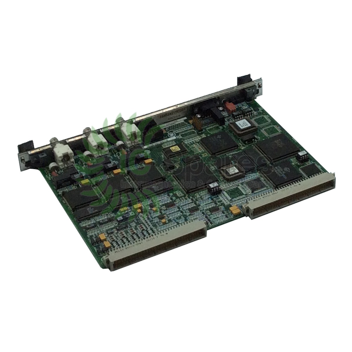
The IS200VCMIH2B Bus Master Controller Board
The IS200VCMIH2B developed by General Electric is a PCB component for the Mark VI system. The Mark VI is one of several systems for gas/steam turbine management. During installation this board is mounted in slot one of the central Control Module and has a primary purpose of using internal communications between I/O cards contained within the card rack or within expansion I/O interface Modules. It also allows for communication to I/O in Protection Modules, I/O in other Control Modules (in triple redundant configurations,) and communications within the main processor card.
IS200VCMIH2B Design and Components
This board is designed with a narrow front faceplate that includes openings for many components, including three LED indicators, a reset switch, a serial port connector, eight LED indicators labeled ‘Module,’ six LED indicators labeled ‘R/S/T,’ three LED indicators and a DIN connector.
These components are wired in to the surface of the Circuit Board. It features two backplane connectors located along its back edge and a vertical pin connector located near the front faceplate as well as a male vertical pin ribbon connector. The board has a transformer located behind the DIN connector that is mounted into the front faceplate. Additionally this board is populated with many resistors, integrated circuits, capacitors and diodes.
The IS200VCMIH2B developed by General Electric is a PCB component for the Mark VI system. The Mark VI is one of several systems for gas/steam turbine management. During installation this board is mounted in slot one of the central Control Module and has a primary purpose of using internal communications between I/O cards contained within the card rack or within expansion I/O interface Modules.
It also allows for communication to I/O in Protection Modules, I/O in other Control Modules (in triple redundant configurations,) and communications within the main processor card.
This board is designed with a narrow front faceplate that includes openings for many components, including three LED indicators, a reset switch, a serial port connector, eight LED indicators labeled ‘Module,’ six LED indicators labeled ‘R/S/T,’ three LED indicators and a DIN connector.
These components are wired in to the surface of the Circuit Board. It features two backplane connectors located along its back edge and a vertical pin connector located near the front faceplate as well as a male vertical pin ribbon connector. The board has a transformer located behind the DIN connector that is mounted into the front faceplate. Additionally this board is populated with many resistors, integrated circuits, capacitors and diodes.