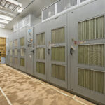
Variable Frequency Drives
[ess_grid_nav id=”filter” alias=”vfd-search”][/ess_grid_nav]
[ess_grid_nav id=”filter-2″ alias=”vfd-search”][/ess_grid_nav]
VFD Products IC Spares Has Available for Immediate Sale
[ess_grid alias=”vfd-search”][/ess_grid]
Frequency-controlled drive solutions ensure movement in almost all industries. The huge range of applications contrasts with a large number of drive components. With the help of a few basic explanations and tips for handling frequency converters, you can easily select the optimal drive system for your application in no time at all.
There are two major types of variable frequency drive on the market: mechanical and electrical. Mechanical VFDs include the following subtypes: Variable pitch drive – a belt and pulley drive where the pitch diameter of one or both pulleys is adjustable, giving a multi ratio and hence a variable output speed.
VFD Types. The AC variable frequency drive and fluid coupling are the most common VFDs used. It involves controlling asynchronous squirrel cage motors and Voltage Source Inverter (VSI) typology. Fans and pumps are among the most common applications for these VFDs.
The integrated family for any drive task
- Medium Voltage AC Drives.
- Low Voltage AC Drives.
- DC Drives.
- SIMOGEAR gear motors.
- Digitalization in drive technology.
- Drives selection and engineering tools.
Choose Siemens Perfect Harmony for your next VFD
- Clean input power: The Siemens Perfect Harmony GH180 4500 HP VFD with 4160 Volt features a clean input power, which helps to protect the drive and the electrical system from disturbances. This is achieved through the use of a filter that removes harmonics and other unwanted transients from the input voltage. This helps to extend the lifespan of the drive and the electrical system, and it also reduces noise and vibration.
- Sinusoidal output power (waveforms): The Siemens Perfect Harmony GH180 4500 HP VFD with 4160 Volts produces sinusoidal output power waveforms, which are gentle on motors and other equipment. This helps to extend the lifespan of motors and other equipment, and it also reduces noise and vibration. Additionally, the sinusoidal output power waveforms help to improve the efficiency of the drive and the motor, which can save energy costs.
- Maximized availability: The Siemens Perfect Harmony GH180 4500 HP VFD with 4160 Volts is designed for maximum availability, with features such as cell bypass and cell redundancy. Cell bypass allows the drive to continue operating even if one or more power cells fail. Cell redundancy provides additional protection against failures by allowing the drive to continue operating even if two power cells fail. This helps to ensure that the drive will be available even if there are problems with the electrical system.
- Extended reliability:The Siemens Perfect Harmony GH180 4500 HP VFD with 4160 Volts is built with proven components and technologies, which helps to extend its lifespan. The drive also features a number of features that help to protect it from damage, such as overvoltage protection and thermal protection. These features help to ensure that the drive will last for many years without any significant problems.
- Exceptional input line performance: The Siemens Perfect Harmony GH180 4500 HP VFD with 4160 Volts has excellent input line performance, which helps to reduce harmonics and improve power quality. This is achieved through the use of a filter that removes harmonics and other unwanted transients from the input voltage. The drive also features a number of other features that help to improve power quality, such as a voltage sag compensator and a reactive power compensation function. These features help to ensure that the drive will not cause any problems with the electrical system, and they can also help to reduce energy costs.
- Ease of installation and maintenance: The Siemens Perfect Harmony GH180 4500 HP VFD with 4160 Volts is easy to install and maintain, thanks to its modular design and intuitive user interface. The drive also features a number of features that help to simplify installation and maintenance, such as a built-in diagnostic system and a remote maintenance function. These features help to reduce the time and cost of installation and maintenance, and they also help to ensure that the drive will be operating correctly.
- Drive topology: The Siemens Perfect Harmony GH180 4500 HP VFD with 4160 Volts uses a cell-based topology, which makes it scalable and flexible. This means that the drive can be easily scaled up or down to meet the specific needs of the application. The cell-based topology also makes the drive more reliable, as it allows for the failure of individual cells without affecting the overall operation of the drive. This helps to ensure that the drive will be able to meet the needs of the application, even if there are changes in the future.
- Proven IGBTs: The Siemens Perfect Harmony GH180 4500 HP VFD with 4160 Volts uses proven IGBTs, which are known for their reliability and efficiency. IGBTs are a type of semiconductor that is used to switch high voltages and currents. They are known for their high reliability and efficiency, and they are also relatively easy to manufacture. This helps to ensure that the drive will be able to operate reliably for many years.
- Linked power cells: The Siemens Perfect Harmony GH180 4500 HP VFD with 4160 Volts uses linked power cells, which helps to improve availability and reliability. Linked power cells are connected in parallel so that if one cell fails, the other cells can continue to provide power to the drive. This helps to ensure that the drive will not experience a loss of power even if one or more cells fail. This helps to ensure that the drive will be able to operate reliably even if there are problems with the power supply.
- Optimized synchronous transfer: The Siemens Perfect Harmony GH180 4500 HP VFD with 4160 Volts uses optimized synchronous transfer, which helps to reduce downtime during power outages. The optimized synchronous transfer is a feature that allows the drive to synchronize with the main power when it is restored after a power outage. This helps to minimize the downtime that is experienced during power outages. This helps to ensure that the drive will be able to resume operation quickly after a power outage.
FAQ's
Frequency converters or also named variable frequency drives are electronic devices that convert a (more or less) fixed frequency and voltage into a variable frequency and voltage. This devices allow electric motors to be operated with a variable speed.
Today, frequency converters are used practically everywhere to operate single-phase and three-phase electric motors with a variable speed. And not just in industrial environments, but in everyday life. Starting from very low power ratings to control washing machine drums up to medium power ratings for pumps used in municipal water supplies.
Variable frequency drives are used in the industrial landscape for the following applications, for example:
- Pumping, ventilating and compressing
- Positioning, processing, moving and machining
These functions are used in many industry sectors:
- Food & beverage industry
- Automotive industry
- Heating, ventilating and air conditioning (HVAC)
- Water and wastewater industry
- Paper industry
- Oil & gas
- Chemical industry
- Logistics
- Wind turbines, hydroelectric power and photovoltaic systems
- Marine
Motor starters – also called soft starters or soft starting devices – are not frequency converters, but devices that simply reduce the voltage. You use them if your motors are connected to line supplies that are either very weak, or to which other loads are connected that are very sensitive to voltage fluctuations. On the other hand, you must use a frequency converter if you wish to continuously control the speed of an electric motor. This offers some significant advantages: Flexibility, process optimization and energy saving.
- Low-voltage converters for motor voltages in the 230 V – 690 V range (single phase, three phase – alternating voltage or three-phase voltage)
- Medium-voltage converters for motor voltages in the 2.3 kV – 13.8 kV range, especially for drive power ratings > 2.5 MW
- DC converters for DC motors comprising a controllable rectifier
- Safety extra-low voltage converters for motor voltages from 24 V DC up to 48 V DC
- Servo drive converters
You can often see terms such as frequency converter, converter, rectifier, inverter, drive converter etc. in literature:
- VFD (variable frequency drive)
- ASD (adjustable speed drive)
- VSI (voltage source inverter)
- CSI (current source inverter)
Here is a brief explanation of some of the commonly used terms used in conjunction with frequency converters:
- Frequency converters to convert the frequency of an alternating voltage or three-phase voltage (single-phase or three-phase) into an AC voltage or three-phase voltage with a different or varying frequency.
- A rotating frequency converter is an electromechanical arrangement comprising a motor and a generator, also called motor-generator set.
- A converter/frequency converter is an electric circuit with which one or several electrical variables can be changed, for example voltage, current and frequency.
- A rectifier is a circuit made up of components to convert AC current or three-phase current into DC current. Converter arrangements, which are used for energy recovery or for braking, must have an active converter at the input that is equipped with controllable power semiconductors.
- Inverters are used to convert DC current into AC current or three-phase current.
- Pulsed converters or PWM converters/inverters (PWM: pulse-width modulation): Using this technique, by suitably selecting the pulse and pause duration (duty cycle or also called mark-space ratio), an output voltage can be obtained. Depending on the pulse frequency, the mean value of this voltage has an almost perfect sinusoidal waveform.
- Voltage-source DC link converters comprise an uncontrolled or controlled rectifier, a DC link with capacitors and an inverter (motor-side inverter). The motor-side inverter (or also just called inverter) generates a three-phase system with adjustable frequency and voltage that impresses a current, which in turn develops the specified motor torque.
- The two main components – line-side converter and motor-side inverter – are connected in the DC link. For current-source DC link converters, this comprises a reactor to smooth the current, and for voltage-source DC link converters, a capacitor to smooth the voltage.
The speed of an electric motor depends on the frequency of the supply voltage and the number of poles that the rotor has. These attributes are fixed (with the exception of pole-changing motors – sometimes called multi-speed motors) and cannot be changed.
Using a frequency converter, the motor voltage and its frequency can be controlled over a wide range, and in turn, its speed.
Operated with a converter, the motor speed can be controlled, the motor can be braked and energy can be recovered (regenerative feedback into the line supply).
In addition to a frequency converter and motor, several other components are required to engineer a variable-speed drive system:
- Line contactor or circuit breaker
- Power cable between the converter and motor
- Fuses at the input
- Line reactor or line filter
- Output reactor or sine-wave filter
- Communication between the converter open-loop control and a higher-level control system
- Air ducts for the cooling air intake and discharge for the converter, possibly with filter
- Cooling system for water-cooled converters
As a result of the closed-loop control, the motor precisely provides the power that the process requires – and no more. For applications where braking is required, you must select a converter that can feed back the electrical energy – that is generated when braking – into the line supply.
Examples:
- Conveyor belts
- Hoisting equipment and cranes
- Expansion turbines
- Test stand drives
- Wind turbines, hydroelectric power and photovoltaic systems
You use a braking resistor if your drive system must be braked or brought to a standstill – especially when a fault situation is involved. Resistors located in the DC link absorb the drive train kinetic energy and convert this into heat (thermal energy).
You should not confuse a braking resistor with a holding brake. A holding brake only ensures that the driven machine that you are controlling does not cause the drive train to move (for example, important for cranes and inclined conveyor sections).
Two filter types come into consideration when using a frequency converter:
- Line filters prevent harmonics, generated by a frequency converter, from being injected back into the line supply and disturbing other loads connected to the same line supply.
Depending on the requirements of your system or your power utility company, line filters can either be LC filters (sine-wave filters) or line reactors. The latter are sometimes called commutating reactors. - Output filters protect your motors against the steep voltage edges inherently generated by an inverter. These filters are required if the cable between the inverter and the motor is very long.
In cases such as these, reflections and voltage transients can occur on cables, which can destroy the insulation of your motor. You can use either sine-wave filters or dv/dt limiting reactors.
In addition to product standard IEC 61800-5-1, which applies to adjustable speed power drive systems (variable-speed drive systems), standards, regulations as well as country-specific specifications, which are specified by users, plant and system operators and power utility companies, must be increasingly taken into account. These include requirements relating to the line quality for example. The predominant reason for this is that increasingly active converters (with controllable power semiconductors) are being connected to grids, for example, for photovoltaic and wind turbine systems. Other examples include Namur connections, to address connection requirements relating to areas of the chemical industry, as well as requirements relating to ruggedness as are demanded for maritime applications, and which are verified in the form of marine certifications.


